Guangzhou Lvyuan Water Purification Equipment Co., Ltd. é um fabricante de filtros industriais fundado em 2009 que projeta e fabrica carcaças de filtro de aço inoxidável, tanques de água estéril de aço inoxidável, elementos de filtro, sacos de filtro, materiais de ultra-polímero e produtos de filtro sinterizado. Os compradores escolhem a Lvyuan devido ao apoio OEM/ODM, ao controlo de qualidade ISO9001 e às certificações de vários países.
Guangzhou Lvyuan Water Purification Equipment Co., Ltd.
Esquema P&ID da linha de engarrafamento de bebidas para pré-filtros e filtros finais
Meta Description: Beverage Bottling Line P&ID guide to prefilters, final filters, pressure monitoring, sanitation paths, and the controls that protect the filler.
Excerpt: A useful filtration P&ID shows how product moves, how each filter is tested and cleaned, and what stops an unsafe fill. This guide examines the design decisions and documented failures that a simple two-filter sketch can hide.
Tags: beverage bottling P&ID, beverage prefiltration, final membrane filtration, sanitary piping, filter differential pressure, bottling line CIP
Esquema P&ID da linha de engarrafamento de bebidas para pré-filtros e filtros finais
Draw the boundary. If a beverage filtration P&ID ends at two boxes labeled “pre filter” and “final filter,” it leaves out the decisions that determine whether the filler receives treated product, whether an operator can isolate a failed cartridge, and whether cleaning solution can reach every product-contact surface.
What, exactly, is that drawing supposed to control?
I treat the P&ID as a record of physical routes and operating decisions. It should identify the feed source, pump, filter housings, valves, instruments, drains, vents, cleaning connections, sample points, and filler interface. It should also make the permitted states intelligible: production, cleaning, sanitization, integrity testing, filter changeout, and fault response.
That standard is demanding because “beverage” covers incompatible processes. Bottled water, a pulpy juice, carbonated soft drink, wine, and an aseptically filled low-acid beverage cannot inherit the same filter sequence or the same hazard controls. A drawing that looks tidy across all five may be too vague to build any one of them safely.
What is the job of each filter?
A prefilter protects the downstream process; a final filter performs the last specified filtration duty before filling. Those duties must be stated separately.
An upstream screen or basket can catch fragments large enough to damage a pump or overwhelm finer media. A bag or depth cartridge can reduce particles and haze that would shorten the life of the last filter. The final element may be a polishing cartridge, a membrane selected for microbial reduction, or another validated treatment arrangement. Its identity depends on the product, the target contaminants, and the rest of the process.
I would reject a specification that simply says “5 µm prefilter, 0.2 µm final filter” without defining the rating method, the organism or particle target, the product matrix, and the test used to verify performance. A nominal particle rating and a validated microbial retention claim are different statements. So are a membrane cartridge and the housing into which it fits.
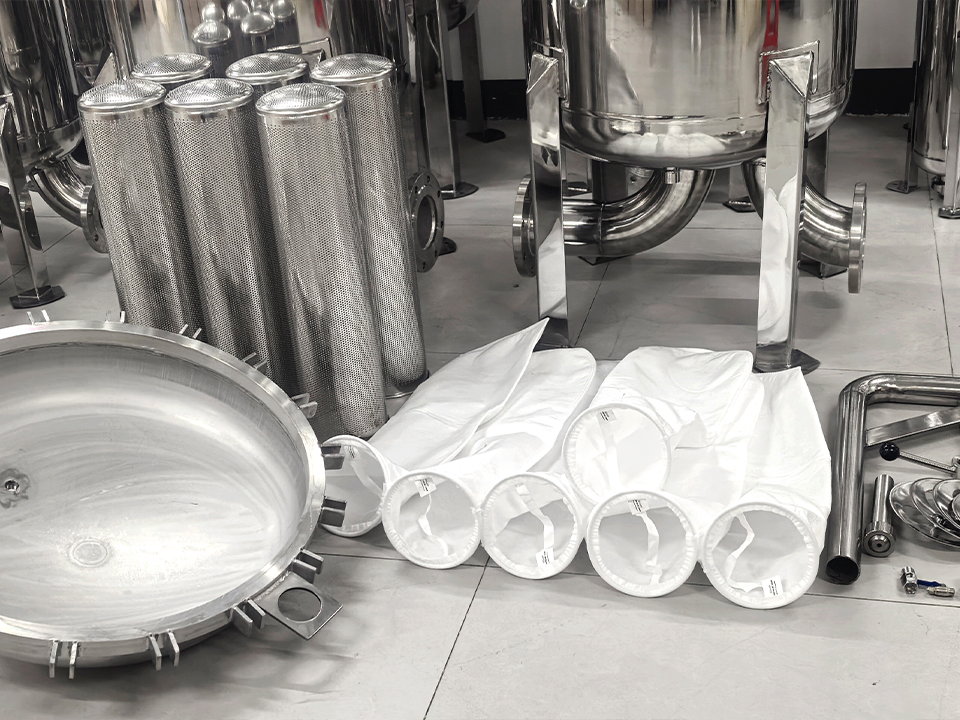
For a coarse upstream duty, a stainless steel basket strainer for pipeline debris is a product category worth examining. The linked unit is presented for industrial pipeline protection, with selectable coarse mesh or perforations. That does não establish its suitability for direct product contact on a sanitary bottling line. Confirm cleanability, surface finish, seals, drainage, pressure rating, and the required food-contact documentation before placing any such device in the product path.
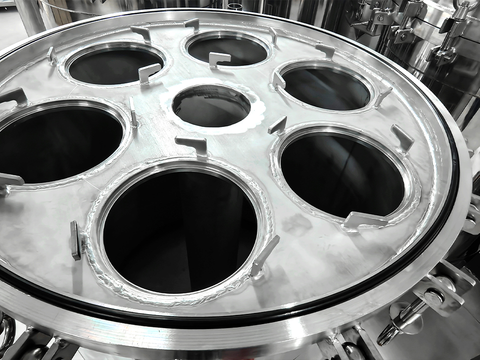
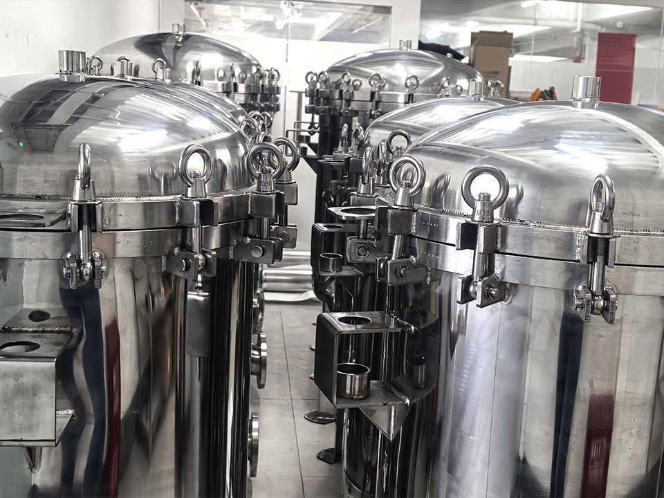
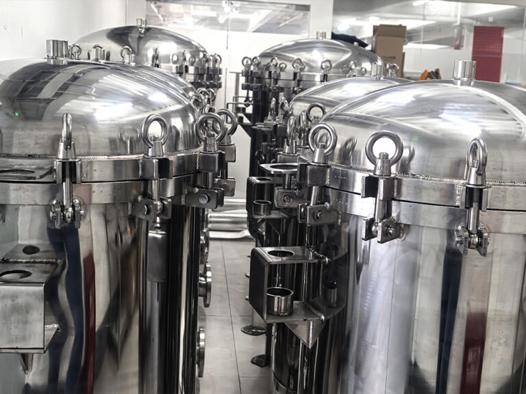
The same qualification applies to a side-entry stainless steel bag filter housing for prefiltration. Its industrial prefiltration role may make sense upstream of a finer stage, but its closure, inlet geometry, bag seal, and cleaning method need a product-specific review. Stainless steel alone is not a hygienic design specification.
Establish the process boundary before drawing symbols
Start at the last well-defined upstream vessel and end at the filler inlet. Mark every place where product, water, cleaning solution, sanitant, gas, or ambient air can enter that boundary. Then ask whether each route exists during production, during cleaning, or in both states.
For a straightforward, noncarbonated line, the working sequence might be feed vessel, transfer pump, coarse protection if needed, prefilter, final filter, controlled transfer to the filler, and filling heads. That sentence is a starting hypothesis. It does not settle the location of a heat-treatment step, deaerator, blending tank, buffer vessel, carbonation stage, or aseptic boundary.
I want five operating facts on the drawing package before anyone chooses a housing:
Product and duty: beverage composition, solids load, viscosity range, temperature, and the identified hazard or quality target.
Demand: maximum filler flow, normal flow, startup flow, and the duration of a production run.
Treatment claim: what the final stage is intended to remove or reduce, and what evidence will support that claim.
Cleaning method: manual removal, clean-in-place (CIP), hot water, chemical sanitation, steam where appropriate, and the permitted sequence.
Disposition: what happens to product when a filter alarm, failed integrity test, valve-position mismatch, or sanitation failure occurs.
Consider a filler running at 20,000 bottles per hour with 600 mL in each bottle. Its nominal liquid demand is 12,000 L/h. That arithmetic is useful; it is not a filter-sizing result. Allowance for starts, stops, recirculation, viscosity, fouling, available pump head, and the usable life of the cartridge still matters. A supplier who quotes only a clean-water flow at room temperature has answered an easier question.
What a sanitary filter piping and instrumentation diagram must show
A credible bottling line filter schematic gives each stage its own equipment tag and measurable pressure loss. One practical convention is P1 immediately before the prefilter, P2 between the prefilter and final filter, and P3 immediately after the final filter. Then P1 − P2 describes the prefilter differential pressure, while P2 − P3 describes the final filter differential pressure.
The distinction matters. If the drawing shows only one pressure gauge upstream of both housings and another downstream of both, a rising total pressure drop cannot reliably tell operators which element is loading. If a hose, valve, or instrument connection sits between P2 and a housing, even the apparently simple calculation needs review. Tap location is part of the measurement.
The P&ID should identify:
Flow direction, line numbers, nominal sizes, materials, and the product-contact boundary.
Isolation valves on each housing, with a documented method to prevent an unintended bypass.
Pressure instruments at the positions needed to assess each filter stage; local gauges alone may be insufficient if the control system must alarm or record a trend.
High differential-pressure alarms, with setpoints established from the selected element and process conditions.
Vents at appropriate high points and drains at appropriate low points, including their safe destinations.
Sampling points with a defined sanitary method and an identified purpose.
CIP supply, return, and isolation paths, including how trapped legs are cleaned and emptied.
Integrity-test connections where a testable final membrane is specified.
Relief or overpressure protection where the hydraulic design requires it.
Valve fail positions, permissives, interlocks, and the action taken on instrument failure.
I also want a valve-state matrix beside the drawing. A P&ID tells me what can be connected; the matrix tells the operator what may be connected in production, CIP, sanitation, test, and maintenance. If a manual valve can route unfiltered product around the final element and into the filler, the drawing needs an unmistakable control for that possibility.
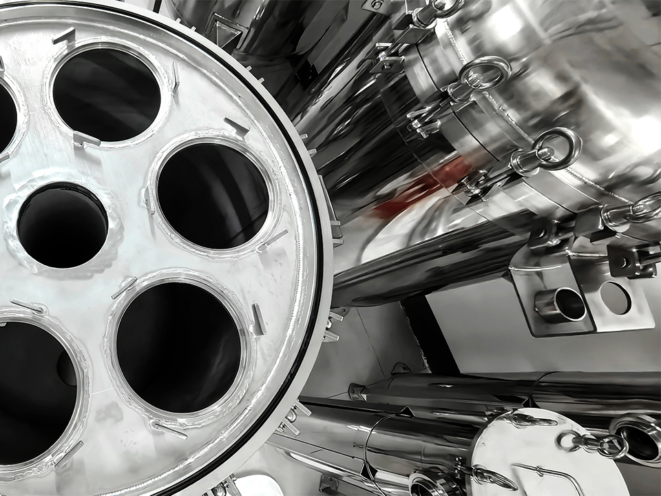
A stainless steel single-cartridge filter housing can be a useful reference when discussing a compact filter stage. But a housing selection is incomplete until the engineer specifies the cartridge interface, seal materials, pressure and temperature limits, drainability, connection style, and cleaning procedure. “Fits one cartridge” does not mean “provides a verified final barrier.”
The prefilter is an economic control with a hygiene burden
Prefiltration can be cheap insurance against premature final-filter plugging. It can also add another vessel, two more gasket interfaces, retained product, cleaning time, and opportunities for an operator to install the wrong element. I would not add a stage because a standard skid drawing happened to have room for it.
Look at the solids and the failure mode first. If the problem is occasional large debris upstream of a pump, a coarse strainer may be appropriate. If the problem is a persistent haze or high colloidal load, a strainer will do little for the final membrane’s service life. If the process carries delicate flavor compounds or intentional pulp, overly aggressive prefiltration may change the beverage itself.
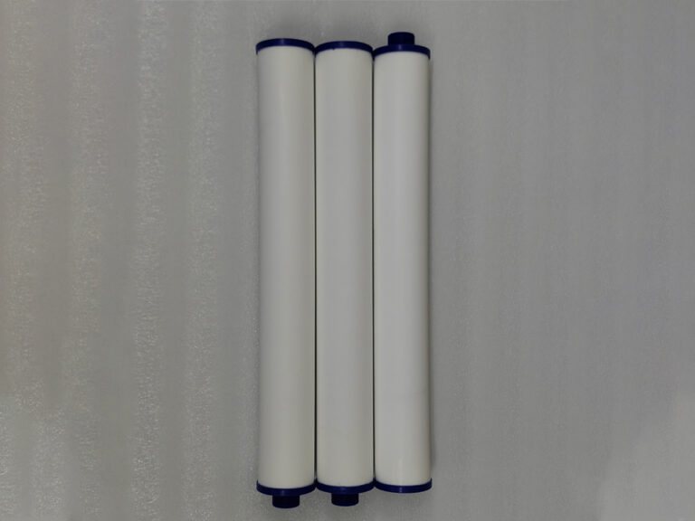
A cartucho filtrante de malha de arame sinterizado lavável ou um stainless steel pleated cartridge could suit a particular upstream solids duty after compatibility and cleaning review. Neither should be described as a microbial final barrier solely because it is made of metal or has a fine published micron rating. Specify the duty, test the product, and record the result.
Here is the hard commercial question: does another prefilter reduce total cost per sellable liter once media changes, retained product, water, chemicals, labor, and downtime are counted? A lower purchase price per element says little about that total. I would ask vendors for trials with the actual beverage at representative temperature and flow, logging pressure loss and throughput until the defined changeout point.
The final membrane is a control only when its performance can be shown
The final membrane filter before bottling sits near an uncomfortable truth: a cartridge can be correctly specified and still be incorrectly installed, damaged, bypassed, fouled, or exposed to conditions outside its validated use. The P&ID therefore needs to support verification, not merely placement.
A membrane’s rating must be tied to the product and the intended removal claim. For context, a major filtration supplier describes 0.45 µm e 0,2 µm options for bottled-water microbial stabilization and higher-retention applications, along with integrity-testable designs; those figures describe particular products and duties, not a universal rule for every beverage. :chatgpt-content-reference{index=”0″}
When a final membrane’s integrity matters, show how it is wetted, isolated, tested, vented, drained, and returned to service. Forward-flow and pressure-decay tests are established nondestructive approaches, but the permitted test pressure and acceptance value belong to the specific membrane and assembly. Temperature, upstream test volume, and the choice of test gas can affect the result. :chatgpt-content-reference{index=”1″}
I would require the drawing and operating procedure to answer a plain question: What happens to product filled since the last acceptable test if the post-use integrity test fails? The answer requires a time boundary, affected-lot identification, a hold decision, investigation, and a release authority. A test port without that disposition process is a fitting waiting for a procedure.
The downstream side deserves particular attention. Once product passes the final filter, every downstream valve, sample point, vent, buffer volume, transfer line, and filler surface becomes part of the protected route. A long, poorly drainable run after the filter can defeat the reason for placing it near the filler. “Final” describes a position in the sequence; it does not make everything after it harmless.
Two FDA cases show where neat drawings fail
I use enforcement records carefully. They show documented findings at particular facilities, not proof that a proposed filter arrangement would have fixed those facilities.
In an August 13, 2024 FDA warning letter to Waiakea Bottling, the agency said a final product-water treatment step was not operating effectively for its intended purpose. The letter describes consumer complaints about visible foreign material in 1-liter bottles and reports third-party findings from one lot, including heterotrophic plate count above 5,700 CFU/mL e Pseudomonas aeruginosa above 2,400 MPN/100 mL. The treatment technology and several operating values are redacted. It would be irresponsible to call this a membrane-filter failure; the documented lesson is that a named final treatment step needs measurable operating limits and a response when performance falls outside them. :chatgpt-content-reference{index=”2″}
A December 26, 2024 FDA warning letter to Baldwin Richardson Foods concerns an aseptic, low-acid non-dairy beverage operation, a different process with its own legal requirements. FDA described missing or inadequate records of critical factors, absent software limits for certain parameters, and distribution before review of relevant records. The letter specifically discusses incomplete capture of aseptic-filling sterilization times and an upper-limit issue involving HEPA-filter air flow. A liquid prefilter and final-filter P&ID cannot substitute for an aseptic process filing, but this case makes the broader engineering point: a sensor tag on a drawing means little unless its limits, alarm behavior, record, and lot-release decision agree. :chatgpt-content-reference{index=”3″}
There is another useful boundary on what filtration can claim. In FDA sampling of 197 bottled-water products collected in 2023–2024, 10 had detectable PFAS; FDA said none of the detected levels exceeded the referenced EPA drinking-water maximum contaminant levels. Those results were published later. Conventional particulate prefilters and microbial membranes should not be marketed as a blanket answer to dissolved contaminants such as PFAS. The hazard analysis must determine whether a different treatment is needed. :chatgpt-content-reference{index=”4″}
Put alarms, valve states, and product disposition on one page
A line can accumulate alarms without gaining control. “High ΔP” is useful only if the operator knows which filter it concerns, what threshold applies, whether the filler continues, and what happens to the affected product. The same goes for low downstream pressure, unexpected flow during an integrity test, an open drain valve, or an incomplete sanitation cycle.
I would build the cause-and-effect review around actual states:
Production permitted: correct element installed; required sanitation and integrity checks passed; drain and CIP routes isolated; product route confirmed; instruments available.
Approaching changeout: stage-specific differential pressure crosses a warning threshold; operations plan a controlled stop or changeover under the approved procedure.
Production inhibited: a defined critical parameter fails or the required final-barrier verification is absent; the filler cannot receive product through an unapproved route.
Product held: the event may have affected filled units; the system records a start time, end time, batch or lot range, and disposition owner.
Return to service: corrective work, sanitation, testing, and documented authorization are complete.
These are design requirements to evaluate, not universal setpoints. A pressure limit copied from another cartridge, another flow rate, or another beverage could create nuisance trips or allow the selected element to operate outside its instructions. The drawing should point to controlled specifications for those values and identify who may change them.
An emergency bypass is especially easy to rationalize during commissioning. If the final filter is the identified control for a relevant hazard, a bypass valve that can send untreated product to the filler is not a convenience feature. Its physical arrangement, lock or access control, indication, and operating prohibition need explicit review. A software warning cannot reliably rescue an unlabeled manual route.
CIP paths are part of the filtration design
Cleaning is where a plausible P&ID often becomes an unusable one. Product flow may run smoothly through a housing while CIP liquid takes a shortcut, leaves an air pocket at the top, or fails to drain the bottom. A filter element may need removal before a particular cleaning cycle, while the bare housing still requires complete exposure and drainage. Those choices belong in the line design.
Show the CIP supply and return connections at their real tie-in points. Mark where product and CIP can be separated, where the cleaning solution exits, and whether the filter housing is cleaned with the element installed. Identify vent operation and any pressure limit during a cycle. If the final membrane requires a separate sanitization or integrity-test sequence, show the necessary connections and isolation valves. Then verify the sequence against the element manufacturer’s instructions and the site’s cleaning validation.
I am skeptical of the phrase “CIP compatible” without a defined circuit. It does not tell me that the closure, seals, cartridge core, ports, and downstream piping see the required conditions for the required time. Nor does it tell me how rinse water is kept out of released product. Conductivity, temperature, flow, time, or another parameter may be monitored for a particular cycle; the approved procedure must state what counts as completion.
For a product-contact housing, I would request a drainability check and an inspection of the actual installed orientation. A beautiful vessel tilted by field piping can retain liquid. A vent placed where an operator cannot safely reach it may become an improvised hose connection. Field fit is not a minor drafting matter here.
Compare the stages before approving a purchase order
Position on the line
Typical purpose
Evidence I would request
P&ID detail that often gets missed
Coarse strainer, if justified
Catch larger debris and protect upstream equipment
Product trial, throughput and ΔP trend, compatibility
Separate upstream and downstream pressure taps; changeout isolation
Fine prefilter, if justified
Extend final-membrane life for a defined feed
Trial showing benefit per sellable liter
Identification that prevents swapping it with the final element
Final membrane or specified final treatment
Meet the last documented filtration or treatment duty
Product-specific validation and applicable integrity or performance checks
Test ports, downstream boundary, alarms, fail response, lot disposition
Filler interface
Preserve the condition achieved upstream
Sanitation and operating evidence for the downstream route
Every valve, vent, sample point, and retained volume after the final stage
That table should be read against a real product and process. A metal cartridge, for example, may be appropriate for a robust, cleanable solids-removal duty; a flanged stainless steel sintered-cartridge housing does not become a suitable final beverage barrier merely by occupying the final box on the diagram. Ask for the element’s actual retention evidence, the complete housing specification, and the installed cleaning method.
How I would review a beverage bottling line P&ID
First, I trace product from the upstream vessel to the filling nozzle with a marker. Any unexplained branch gets a question. I trace CIP, rinse water, compressed gas, and drains in different passes. Then I review the valve-state matrix against each route. A single shared connection can behave very differently in production and cleaning.
Second, I test the instrumentation logic against realistic faults. If the prefilter loads, can the operator identify it without opening the final housing? If the downstream pressure falls, can the system distinguish a starved filler from a damaged filter assembly? If the pressure transmitter fails, does its failure appear as a fault or as a comforting zero? If power returns after an interruption, does production resume only after the required checks?
Third, I inspect the proposed operating records. Which values are trended? Which events are timestamped? Can quality staff determine what was filled between a last known good condition and the next verified good condition? The Baldwin Richardson FDA findings are a reminder that recording “Pass” without complete upper and lower limits may conceal the event an engineer intended to detect. :chatgpt-content-reference{index=”5″}
Finally, I ask maintenance and operators to walk through an actual element change. Where does retained product go? How is pressure relieved? Can an element be installed backward or in the wrong position? Which gasket is replaced? Who confirms that the housing is closed, sanitized, and ready? If their answers require improvisation, the P&ID package and procedures are unfinished.
FAQs
What is the difference between prefilters and final filters in beverage bottling?
A prefilter is an upstream filtration stage selected primarily to remove a defined solids load and protect downstream equipment or media, while a final filter is the last specified filtration stage before filling and is selected against a separate product-quality or microbial-control objective, with verification appropriate to that objective. The two stages need distinct tags, pressure measurements, and acceptance criteria.
How do you design a bottling line filtration P&ID?
A bottling line filtration P&ID is designed by defining the product, hazards, operating modes, and filler demand; placing each vessel, filter, valve, instrument, vent, drain, sample point, and cleaning connection on the actual flow paths; and specifying the alarms, tests, permitted valve states, and product-disposition actions associated with each critical condition. Review it with operations, quality, maintenance, controls, and the filter supplier before release.
Is a 0.2 µm final filter always required?
A 0.2 µm final filter is a membrane option used for particular validated microbial-retention duties, but its pore rating alone does not establish that it is required, effective, or compatible with every beverage, because the product, target organisms, treatment sequence, cartridge construction, operating conditions, and applicable regulatory framework determine the appropriate final control. Specify the duty first; select and verify the element afterward.
Where should differential-pressure instruments go?
Differential-pressure instruments should measure the pressure loss across each filter stage at taps positioned to represent that stage, allowing operators and controls to distinguish prefilter loading from final-filter loading and compare each measured value with limits established for the selected element at the relevant flow, temperature, and product condition. A single reading across both housings loses that diagnostic separation.
Can a stainless steel filter housing serve as the final filter?
A stainless steel filter housing is a pressure-containing component that holds an element; it can form part of a final filtration assembly only when the complete housing, cartridge, seals, connections, cleaning method, and installed performance meet the specified product duty and verification plan. The vessel material alone provides no microbial-retention claim and does not establish hygienic suitability.
Request a review of the actual line
Bring the current P&ID, product specification, maximum filler flow, cleaning procedure, intended filter elements, and any available pressure or contamination records to the housing discussion. Ask for a marked-up route review and a written list of unresolved specifications before ordering. That is the point at which a filter quotation can become an engineering decision.